| Section | ||||||||||||||||||||||||||||||
|---|---|---|---|---|---|---|---|---|---|---|---|---|---|---|---|---|---|---|---|---|---|---|---|---|---|---|---|---|---|---|
|
IoT Kit Components
The azeti IoT Kit includes the following components:
- Unipi Neuron S103 IoT Gateway. Main characteristics:
- Industry grade Raspberry Pi 3 based gateway
- 4 Digital Inputs
- 4 Digital Ouptuts
- 1 Analogue Input
- 1 Analogue Output
- 1 1wire port
- Includes an 8GB SD Card with the OS and Azeti SiteController already installed
- For more information check the Unipi documentation here
- Electrical Components:
- Power Supply: Meanwell DR-15-24.
- Input Voltage 85 VAC to 264 VAC, 120 VDC to 370 VDC
- Output Voltage: 24 VDC
- Output Current (max): 0.63 A
- Maximum Power: 15 W
- Main Breaker (controls the power to the whole kit): Siemens 5S
- Rated Operational Voltage: 250 VAC
- Rated Current: 10 A
- Rated Operational Voltage: 250 VAC
- Sensor Breaker (controls the power to the sensors)
- Rated Operational Voltage: 250 VAC
- Rated Current: 16 A
- Rated Operational Voltage: 250 VAC
- Relay Finder 40.61.9.024.0000. Controlled by the Unipi Digital Output (DO1) is connected to the AC power of the kit and to the AC output power socket.
- Coil Voltage: 24V DC
- Contact Voltage: 250VAC
- Contact Current: 16 A
- Power Supply: Meanwell DR-15-24.
- Sensors and Outputs
- Inepro Smart Energy Meter Pro1 Modbus: Smart Meter that reads the overall power consumption of all the elements included in the kit, plus whatever is connected to the AC power output. It also gives voltage, current and frequency readings.
- Nominal voltage (Un) 230V AC
Operational voltage 195-253VAC
Basic current (Ib) 5A
Maximum rated current (Imax) 45A
Operational current range 0.4%Ib-Imax
Overcurrent withstand 30 Imax for 0.01s
Operational frequency range 50Hz ±10%
Internal power consumption ≤2W/Phase - ≤10VA/Phase
- For more information check the manual here
- Autosen AC004 – Capacitive sensor. Capacitive sensor that sends a signal whenever detects some object near this upper side (green). Connected to a Digital Input of the Unipi (DI2)
- Magnetic Door Contact: Mounted on the enclosure, detects when the lid is opened or closed. Connect to a Digital Input of the Unipi (DI1)
- LED: Mounted on the top side of the enclosure, is controlled by a Digital Output of the Unipi (DO2). The default behavior is that the LED is turned on whenever the lid is opened.
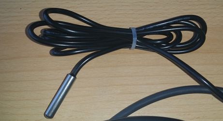
- 1-Wire Temperature sensor DS18B20
Measures Temperatures from -55°C to +125°C (-67°F to +257°F)
±0.5°C Accuracy from -10°C to +85°C
- Inepro Smart Energy Meter Pro1 Modbus: Smart Meter that reads the overall power consumption of all the elements included in the kit, plus whatever is connected to the AC power output. It also gives voltage, current and frequency readings.
Diagrams and Pictures
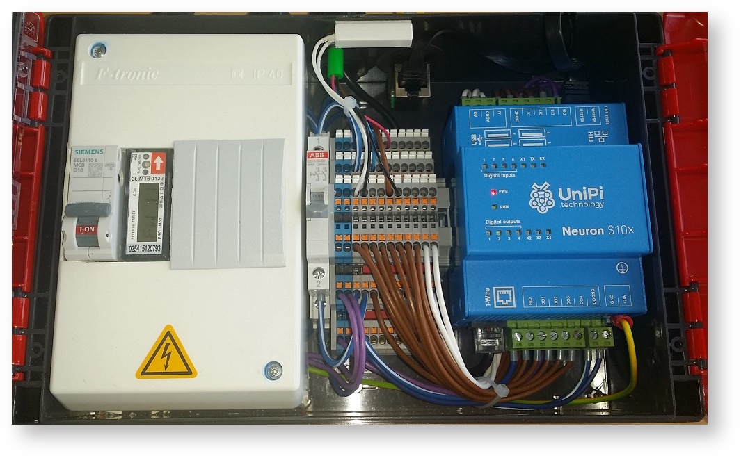
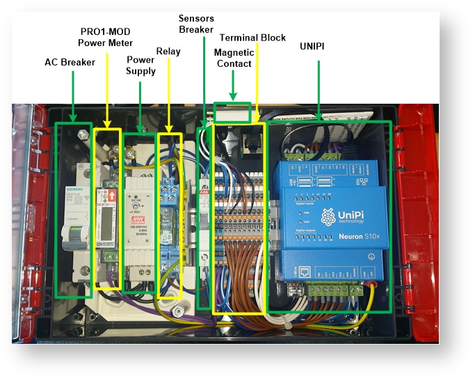
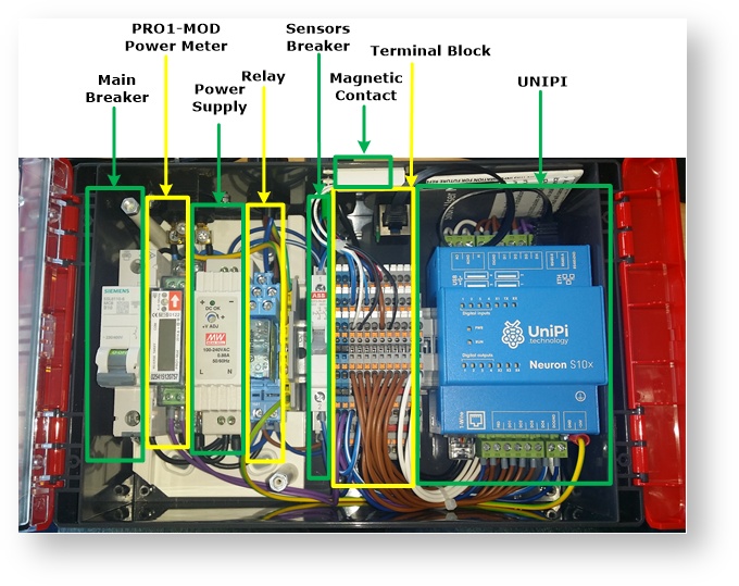
Top View
Top Side View
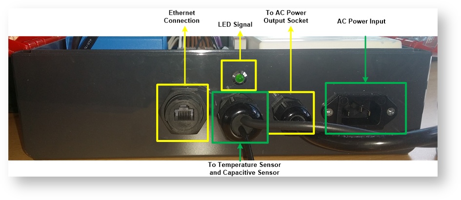
Right Side View
Sensors
Temperature Sensor
Capacitive Sensor
AC Power Output
Basic Setup procedure
To setup the IoT kit follow this steps:
Connect the provided PC Power cable to the AC Power Input on the top side.
Warning Make sure to connect to the AC Power Input and NOT to the AC Power Output socket (see previous pictures)
Connect the Ethernet Network Cable to the Ethernet Input port on the top side.
Info The Ethernet port is configured to work with DHCP. If no DHCP is enabled the default IP will be 192.168.100.1. The IoT Gateway also has a wlan interface. To learn how to configured it go to the WLAN Configuration section in this document.
- Switch ON the Main Breaker
- Switch ON the Sensors Breaker
...
